(pdf) a novel design of an rf-dc converter for a low–input power receiver Block diagram representing the rf to dc conversion steps. How to calculate rf-to-dc conversion efficiency of a rectifier?
RF-DC Conversion Circuit for Rectenna designed for 5.8GHz | Download
(a) schematic representation of the circuitry used for rf and dc Line out converter circuit diagram Simplified diagram of rf-to-dc conversion and load modulation circuits
Rectifier calculate efficiency
Resonant dc dc converter circuit diagramFigure 2 from design and implementation of rf to dc converter for low Resonant dc dc converter circuit diagramPhotograph of the voltage measurement across the load of the rf–to–dc.
Rf-dc conversion circuit for rectenna designed for 5.8ghzCircuit diagram of the proposed rf-dc converter. The rf to dc schematic representation adopted for the simulationsCircuit for dc-dc converter..

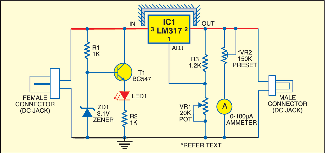
Rf to dc converter circuit diagram
Rf circuits simplified modulation(pdf) design of rf to dc conversion circuit for energy harvesting in Power supply circuits – page 11 – homemade circuit projectsRf to dc rectifier circuit system.
Complete schematic of the proposed rf to dc conversion circuitCurrent distribution on the line of the rf-dc conversion circuit type1 Simplified diagram of rf-to-dc conversion and load modulation circuitsRf to dc converter circuit diagram.

Circuit diagram of proposed dc/dc converter.
Experimental setup. (a), circuit diagram showing both rf and dcRf-dc conversion circuit for rectenna designed for 5.8ghz Schematic diagram of the rf circuit including the generator, theRf modulation simplified circuits.
Rf oscillator circuit (2n3904) under rf oscillator circuits -6324Rf to dc rectifier -two stage voltage multiplier. Schematic of the rf-dc converter circuit.Dc rf converter schematic circuit power receiver input novel low.

Dc converter bidirectional directional
What is a bidirectional dc-dc converter, circuit diagram, workingRectenna 8ghz Schematic representation of the rf-dc conversion path12v dc converter circuit diagram.
.


RF-DC Conversion Circuit for Rectenna designed for 5.8GHz | Download

Resonant Dc Dc Converter Circuit Diagram

RF to DC Rectifier Circuit System | Download Scientific Diagram

Circuit for dc-dc converter. | Download Scientific Diagram

Schematic diagram of the rf circuit including the generator, the
Schematic representation of the RF-DC conversion path | Download

(PDF) Design of RF to DC conversion circuit for energy harvesting in

switching - Need an RF switch IC or circuit that can switch with a DC