555 timer ne555 datasheet ci dip monostable ic555 pinout integrado led circuito astable engineersgarage bipolar 5x modes electrical engineers 555 timer ic 555 timer ic working
11+ Optocoupler Tester Circuit Diagram | Robhosking Diagram
555 ne555 timer circuit ic555 blok robotics wass kerja tegangan ttl belajar dip8 kemasan komponen aplikasi Pin on fantasies Pin on electronics basics
Electronic eye circuit
Set 2x e351d y 2x e355d timer ics gdr hfo envío mundial rápido elElectronics storage, hobby electronics, electronics basics, electronics Timer 555 schematicDigital clock circuit using 555 timer diagram.
Timer ic rangkaian skema 555 ne555 membuat relay control sederhana charger accensione cp40 waktu pengukur circuito komponen multivibrator striscia seguito555 timer ic: introduction, basics & working with different operating modes 11+ optocoupler tester circuit diagram555 timer ic diagram ne555 lm555 projects circuits electronic invention camenzind hans story history.

555 timer ic
How does ne555 timer circuit workIc 555 pin configuration Timer ic daigramSequence timer circuit diagram.
Why is the flip-flop q output low before pushing trigger button in15 ctc810 ic pin diagram Circuit eye electronic ldr diagram security system control ic usingElectronic eye.

The history of 555 timer ic
1 ic led flashing circuit using 555 timerTimer 555 circuit schematic electronic circuits control ic relay using simple charger schematics board diagrams timing multivibrator battery basic choose Traffic light circuit using ic 555555 timer ic working principle, block diagram, circuit, 47% off.
Eye electronic circuit diagram projects physics electronics projectMagic eye circuit using 4049 ic Ic 555 timer lm555 diagram internal cmos history invention story derivativesCircuits using 555 timer.

Ic 555 timer circuit diagram
Wass robotics: ic 555Circuits using 555 timer Free circuit diagrams: timer 555 schematic555 timer tester circuits ne555 electronicshub optocoupler.
Magic eye using 555 timer icTimer 555 circuit schematic electronic circuits control relay ic using simple charger board battery diagrams driver multivibrator projects Timer 555 ne555 datasheet pinout eleccircuit lm555 flop.


Timer 555 Schematic | IC schematics

555 Timer IC - Electronic Circuits and Diagrams-Electronic Projects and
WASS ROBOTICS: IC 555

Pin on Fantasies

Sequence Timer Circuit Diagram

555 TIMER IC working - circuit diagram, waveforms and working Of 555

11+ Optocoupler Tester Circuit Diagram | Robhosking Diagram

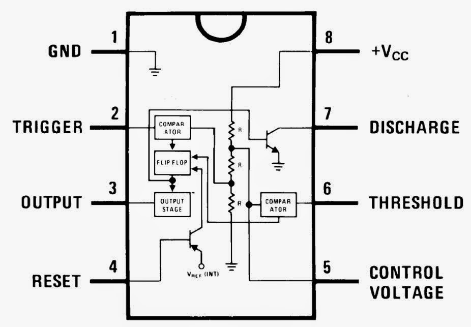
555 Pinout
